Pull pin security alarm circuit.
Burglar alarm project report pdf.
Academia edu is a platform for academics to share research papers.
Working of security alarm circuit.
Development of a simple sound activated burglar alarm system pdf.
The burglar alarm is one of the most reliable means to secure a house or a work place.
Burglar alarm system is an important part of home security systems this burglar alarm project is based on pir sensor um3561 and speaker.
Pir sensor used to detect body motion and um3561 speaker to produce police siren after any movement detection.
This project deals with a model of laser security alarm system design.
One of them can put in front of the locker while another one can be placed on the front door.
Today there are different types of home security systems available in the market and they perform in different ways to detect potential intrusions.
The desired output of your burglar alarm system causes a specified alarm output and quickly responds whenever the sensors identify valid conditions which have activated the alarm.
1 2 objectives of the project.
It is becoming more and more popular among the homeowners because of the consistency with which it performs.
The unit s ability in communicating back to its monitoring system is truly a crucial aspect for determining the efficiency of the alarm.
The first one is a simple burglar alarm circuit using pir sensor arduino a buzzer and a push button switch.
This project is aim at designing a model that could be used to monitor the important parameters of the system and carry out.
My project covers a variety of sub topics like it s working setup uses in life and different aspects of laser security alarm system.
My project provides complete information on the topic laser security alarm system and maximum efforts have been taken to make the project more comprehensive and lucid to understand.
The pir sensor is used to monitor a particular location field for any movement motion.
Now there are dozens of different security systems on the market.
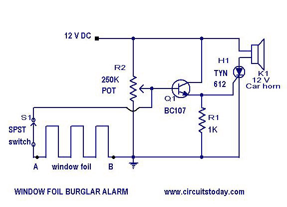
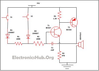
S1 and s2 are the two switches that are used in the circuit so that both can be put in two different places i e.